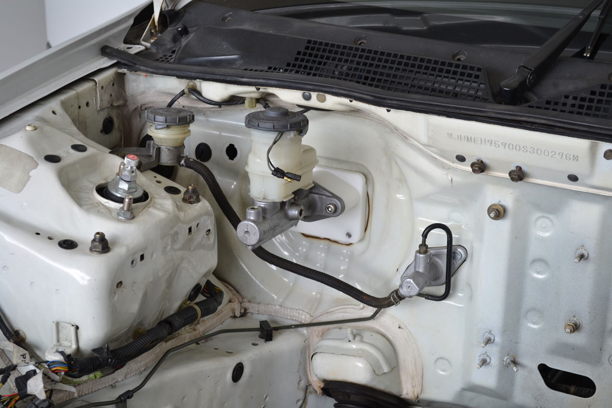
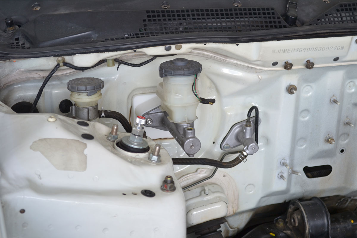
I was excited to get into the garage this morning because yesterday I received a 3d printed version of my latest brake booster delete plate design and I was egar to see how it looked
I have changed the mounting pattern of my booster delete plate to a horizontal two bolt pattern so that I can use Honda EK Civic master cylinders. The previous design used an EF master cylinder and in that mounting style there were limited cylinder sizes available
Second hand EK master cylinders are also going to be in better condition since they newer vehicles
I want to stick with a Honda master cylinders for a few reasons
- Oem reliability
- Cheap replacement cost
- Safety
Although they have a common reservoir the Honda master cylinders are a dual circuit design, meaning that the vehicle has two separate brake circuits (diagonally split on Civics and Integras).
If a brake hose at one corner fails and you press the brake pedal the fluid from that circuit will bleed out however you will still have the brakes on the other circuit to help you stop.
It’s a CAMS requirement (schedule B) that vehicles have dual circuit braking systems for this reason.
This booster delete plate mounts the master cylinder offset upward to match the new mounting hole I drilled in my brake pedal when I changed the pedal ratio (which you must do If you delete your booster)
To the other side of the firewall now
I cut the original accelerator pedal off the brake pedal bracket and mounted a Holden Commodore electronic throttle pedal in it’s place
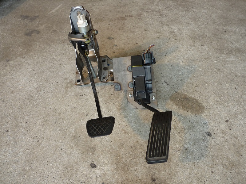
I allowed some for some adjustment of the commodore pedal by slotting the mounting holes (up and down) I was also thinking that if it was drastically out the I could always just bend the pedal
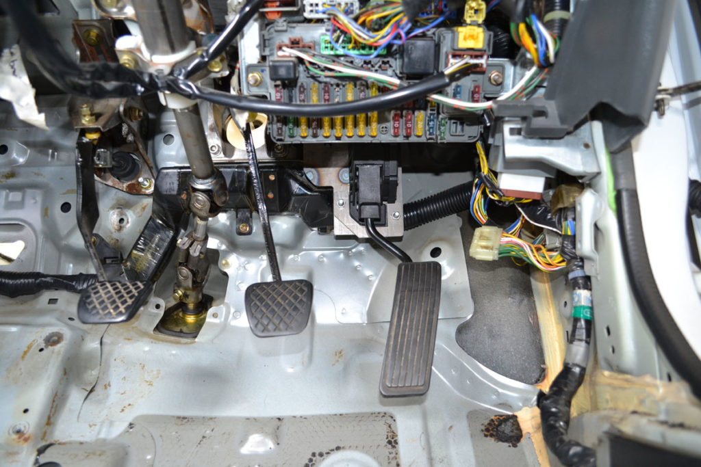
Today I mounted it in place and sat in the drivers seat to try it out
By a complete fluke it is in the perfect position, from what I can tell without driving it at least
Feels just nice beside the brake pedal
The pedal stop on the back of the pedal even contacts the firewall just before the pedal runs out of travel which is ideal
Stoked with that result
I have modified an old knuckle similarly to how I intend to modify my actual knuckles (without the box section obviously hah)
The idea being that I will be able to check the driveshaft lengths, clearances and work out a design for the upper control arm using this beater knuckle
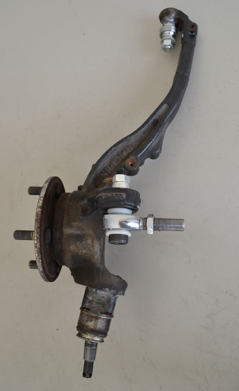
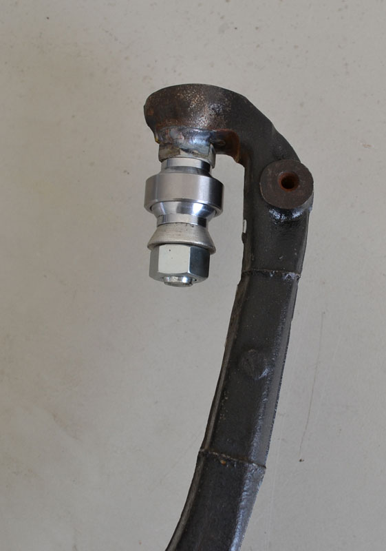
One thing that this exercise has uncovered is that there is not a whole lot of room between the spherical bearing which is to be my new upper ball joint and the knuckle
This is a 1/2″ bolt and 1/2″ spherical so after looking at this I have decided to downsize this to 3/8″ which beacuse the bearing race is smaller gains me another 2.5mm in that gap
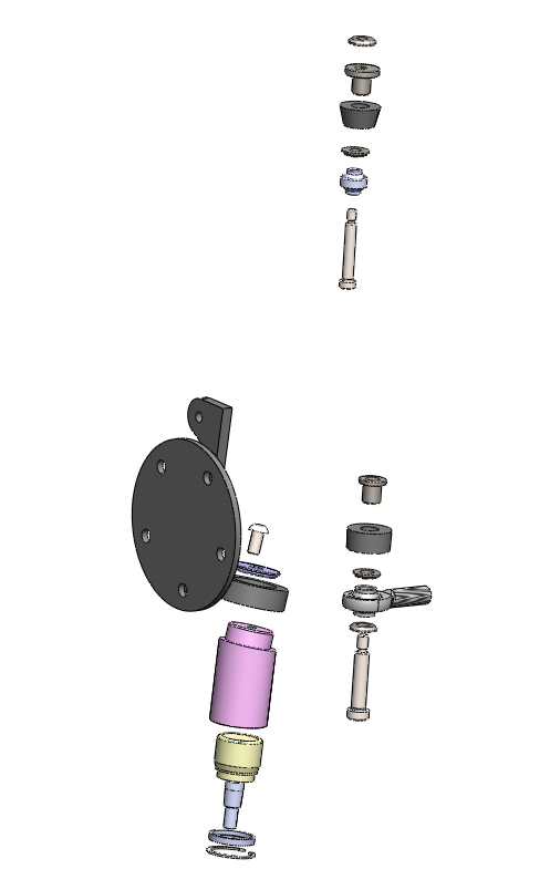
This is an exploded view showing the modification I intend to do to the knuckle
Various bushes and spacers
Before I commit and send my drawings out for the knuckle modification parts I thought I better measure the suspension geometry one last time just to be sure what I intend to is going to work
I pulled the shock out of the LHS and then set the car up as if the ride height was 300mm wheel centre to guard
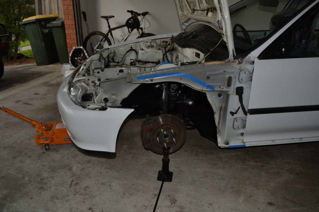
Took a bunch of measurements
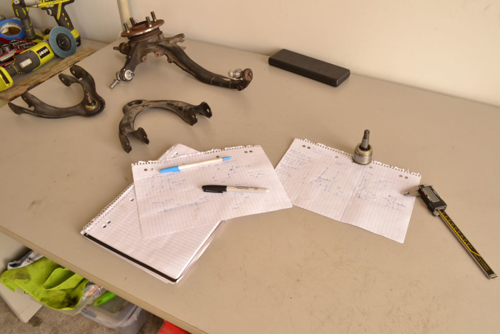
Put those measurements into CAD, I’ve got alot of the components measured and modeled already so I only really need to take a few key measurements and then I can generate a 2d traverse corner model
Then I superimposed the geometry of the modified knuckle and checked that It was all going to work out as intended
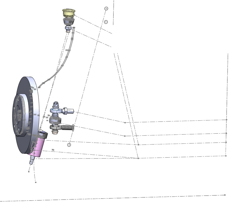
The biggest thing to come out of this is that I can’t quite get the lower ball joint as low as I’d like because it:
- Will hit the inside of the brake rotor
- Hit the inside of the rim
But were only talking like 10mm short of ideal so it’s not a major.
I guess that’s why the later generation touring cars eventually when to 18’s and 19’s!

