In the last couple of posts I covered the process of measuring the front suspension geometry of the Sedan.
From there I went on to figure out the modifications that I need to do to the knuckles to achieve JTCC ride height AND still have sound suspension geometry.
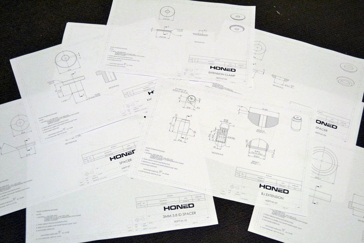
Well I’ve got the drawings done for the parts for the front end!
But before I send those out to the machinist, I thought it best that I check that I will be able to achieve something similar with the rear of the car.
I’m measuring the rear ride height as the distance from the centre of the wheel hub to the apex of the guard.
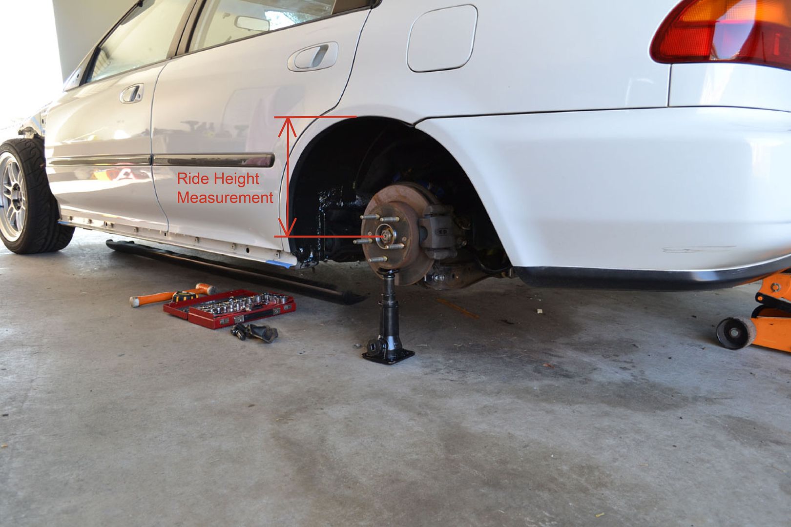
The ride height the car currently is 295mm and I think that the car needs to be 50mm lower to achieve the look I’m after.
I measured the position of all the suspension points at 295mm and then again at 245mm.
In the following comparison shots you can see what happens to the suspension links when you lower the car this much.
Keep in mind too that my trailing arms have already been modified and that my lower control arm mounting points is 25mm further down than stock!
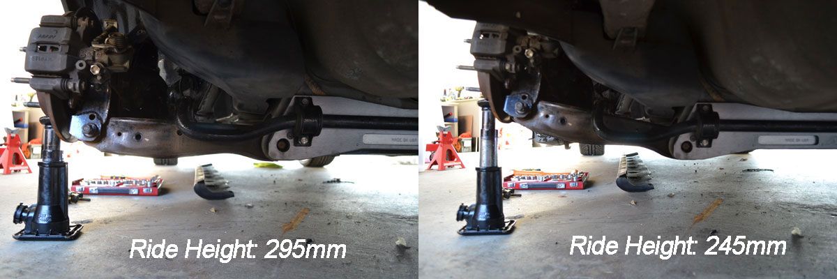
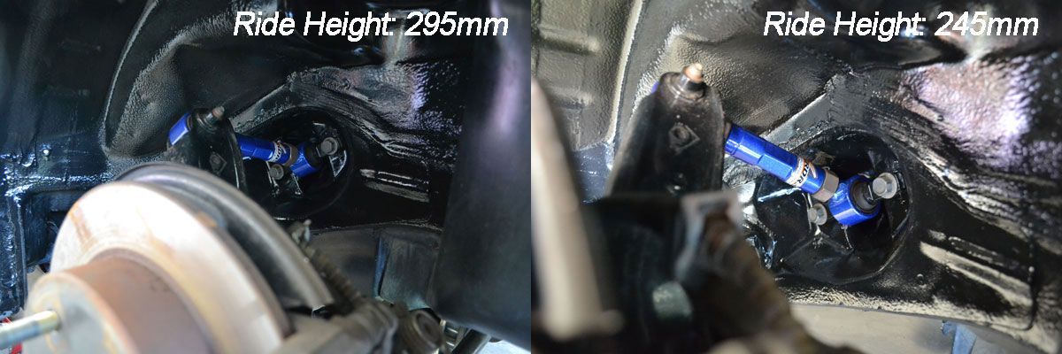
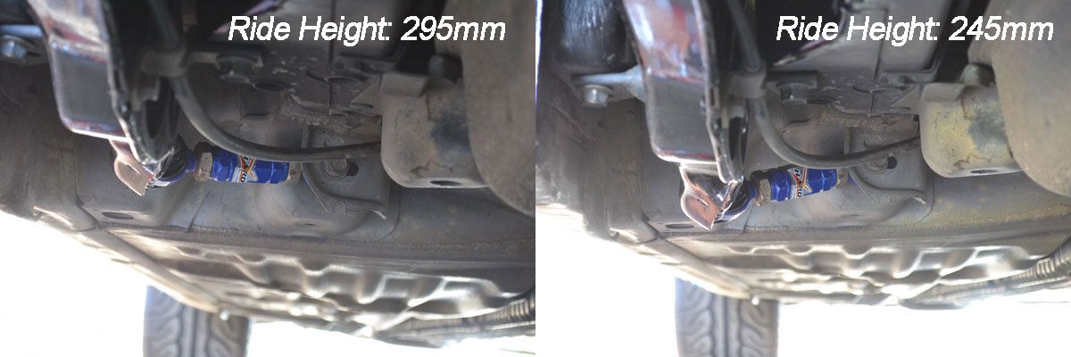
It’s clear looking at these suspension arm angles, I won’t get away with just lowering the car 50mm and use the trailing arms as they are.
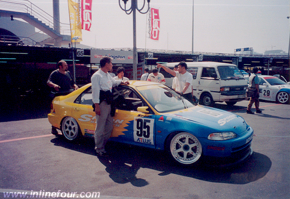
This is what the 245mm ride height looks like with a wheel in place.
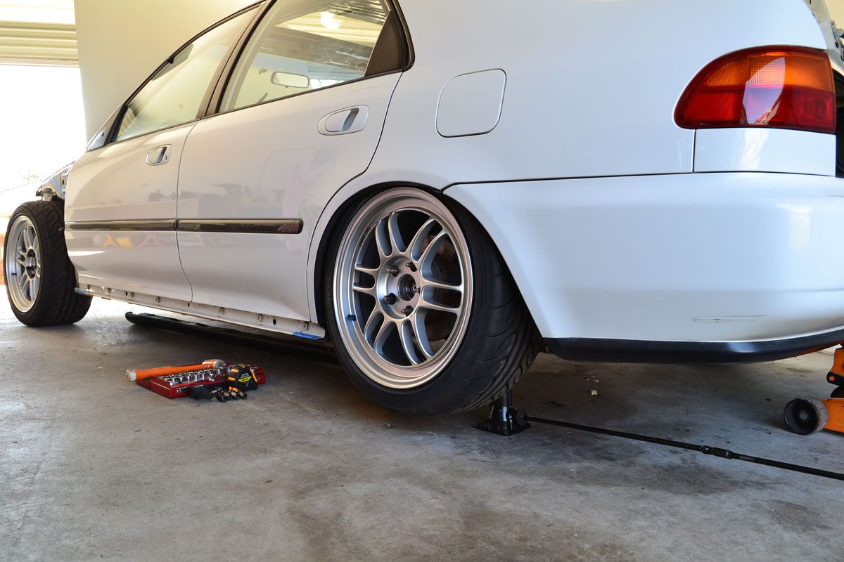
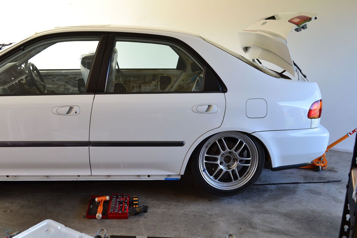
I think it achieves that “edge of the rim level with the guard” look that i’m going for.
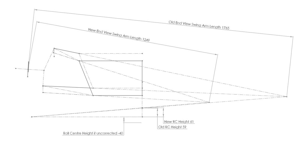
Once I had all the measurements on paper, I plugged the numbers into CAD and compared the geometry between the two ride heights.
With CAD I can determine what the ideal geometry would be, but in the real world some things can’t be moved as much as you’d like.
This could be because they would then interfere with something you can’t relocate, like the rim, or it could be because there is no metal there for you to drill a hole into.
This means there is a fair bit of back and forth between the computer and the garage to work out what can and can’t be done.
Here are the things that I can do:
- Extend the LCA mounting point on the trailing arm downward by another 45mm (70mm lower than stock!)
- Modify where the camber arm mounts to the trailing arm such that the camber arm attaches to the trailing arm 30mm lower than before
- Cut and rotate the front of the trailing arm so that the bit where the toe link mounts is 25mm higher relative to where it was before.
Doing those things will achieve the following:
- Set the rear roll centre height close to what it was before (61mm vs the 59mm I had with my V1 modified trailing arms)
- Give a toe curve that tends to positive toe either side of ride height
- Achieve camber gain comparable to stock
I’m quite possibly the only person that cares about those things haha but I’ll persist down this rabbit hole to satisfy myself.
I already have a second set of trailing arms, gusset plates and lower control arm relocation brackets.
Although I will have to get new relocation brackets made but that’s no big deal.
This is what the longer lower control arm mount relocation brackets look like.
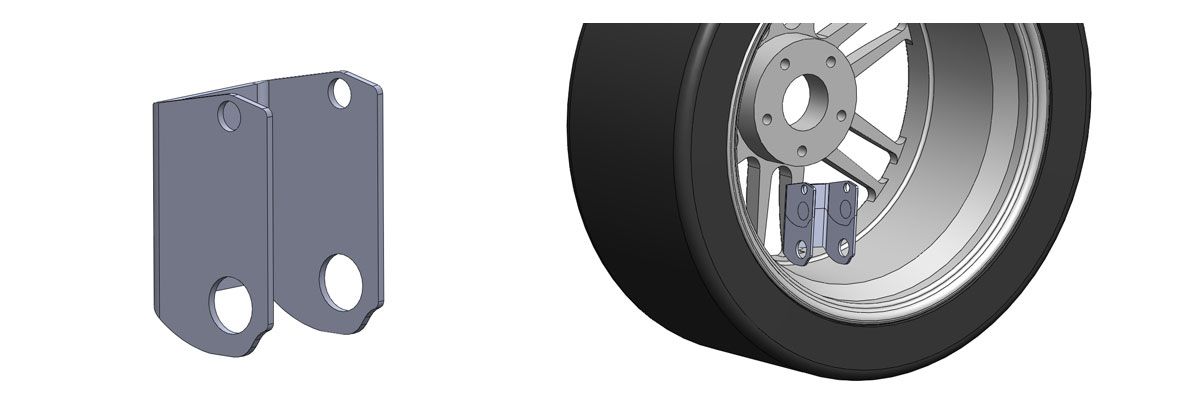
I will have to take care when putting the wheels on and off so that I don’t bang up the inside of my rims as there won’t be a whole lot of clearance there.
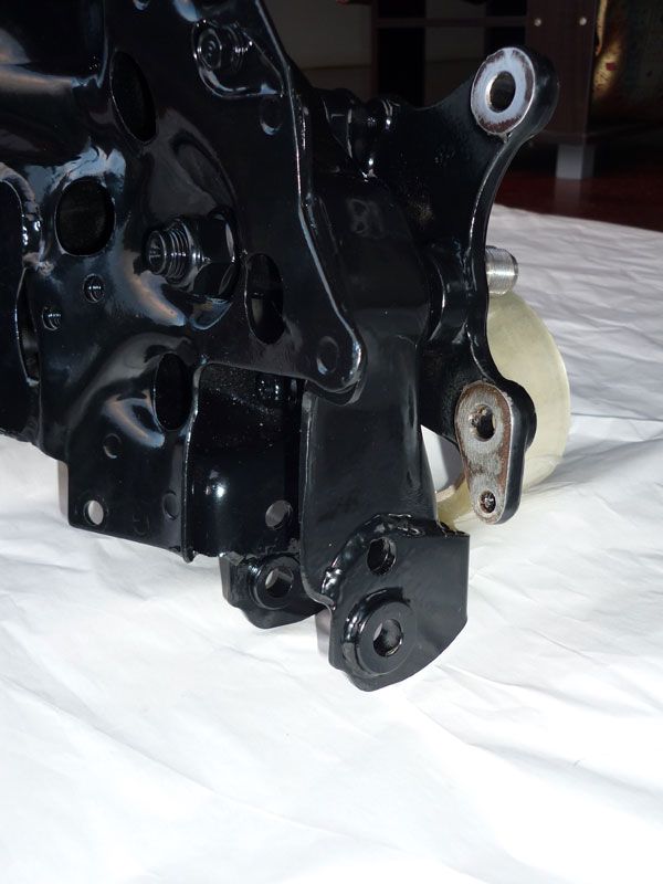
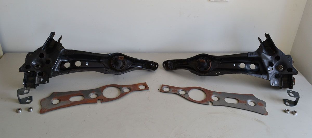
This is a photo of one of the trailing arms which are in the car now.
You can see the original LCA relocation bracket welded on.
That bracket was designed to correct the rear suspension geometry when using 15″ wheels and relocated the LCA mount 25mm downward.
You can think of it as rear roll centre correction, it serves the same purpose as extended ball joints up front.