In the name of giving people something mildly interesting to read before the long weekend we thought we’d share the latest modifications to our EK Civic.
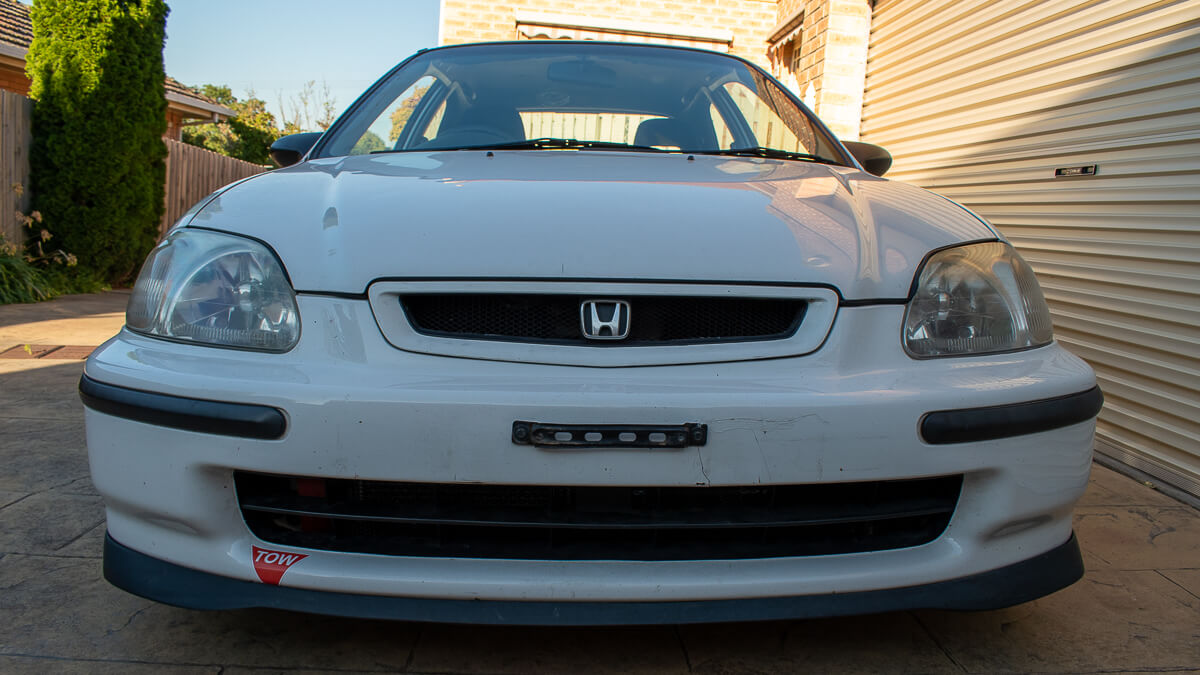
The car is a 96 Honda Civic CXI, CXI being the base model in the Australian market and comes with a D16Y4 a non-vtec sohc engine.
The chassis has been modified with all of the Honed parts like the complete geometry kit and booster delete kit.
At the end 2018, after tracking the car for a couple of years with the stock engine, we put together a turbo kit with Garret T28 and water-to-air intercooler from a bi-turbo Mercedes of some kind.
In its current form it makes 110kwatw.
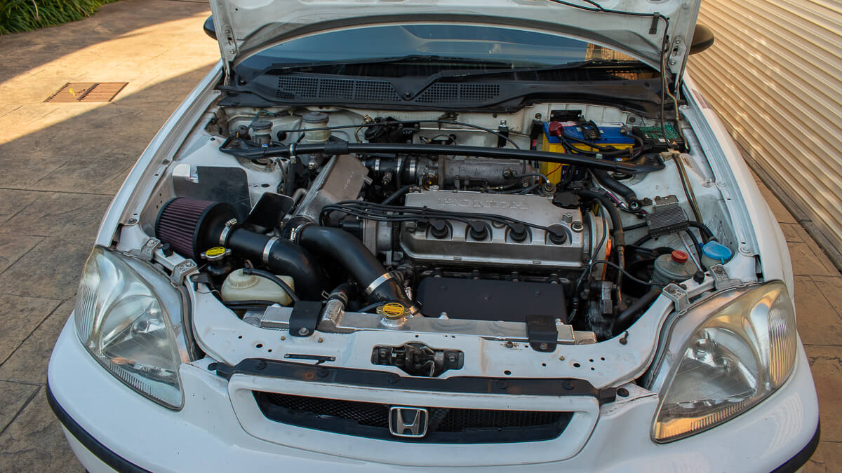
You can see here how the intercooler and charge piping is packed into the engine bay.
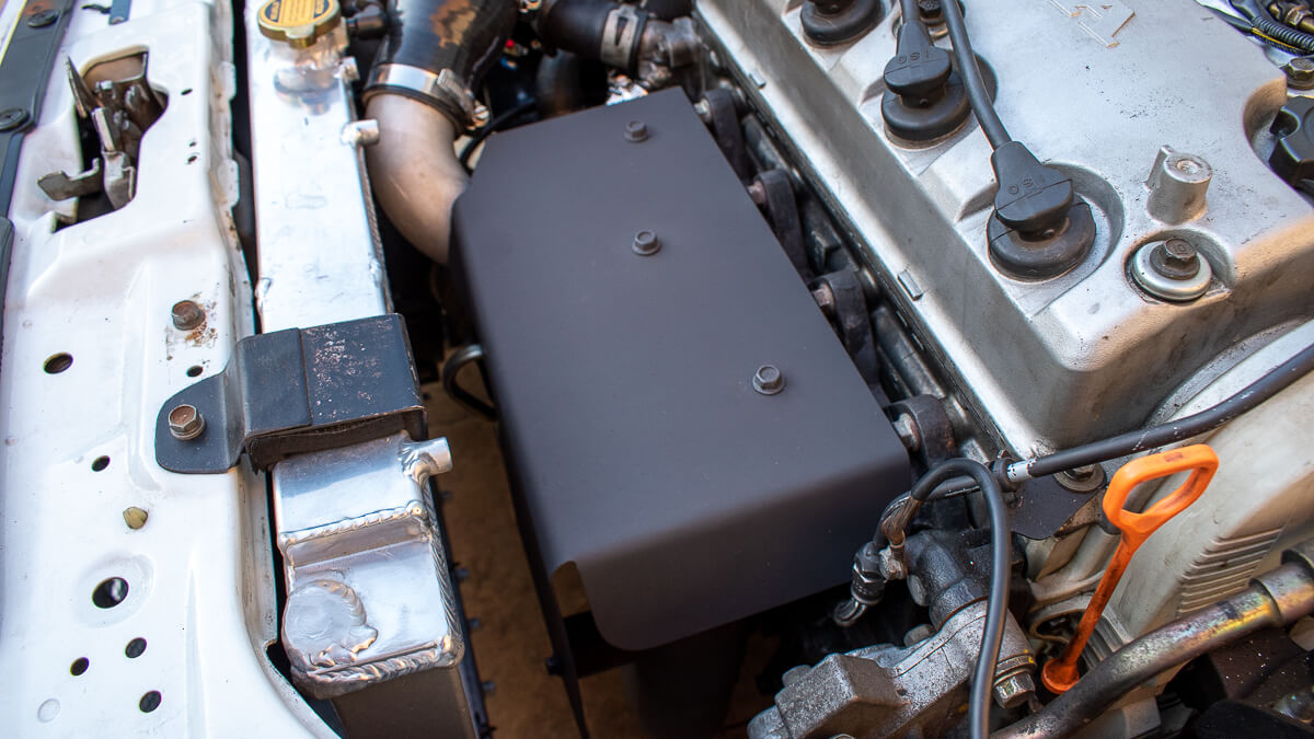
The boxy looking heat shield covering the exhaust manifold and turbo is new.
It’s made from 1mm thick mild steel and replaces a version made from that embossed aluminium material which cracked around it’s fixing points and proceeded to rattle.
The turbo was recently replaced due to bush bearing failure. What you can’t see here is that we have re-worked the waterlines to and from the turbo core focusing on eliminating any tight bends and using 3/8″ steel hardline wherever possible.
Additional heat and chafing protection has also been installed around the oil feed line.
Owners of aftermarket turbo builds will relate to these issues!
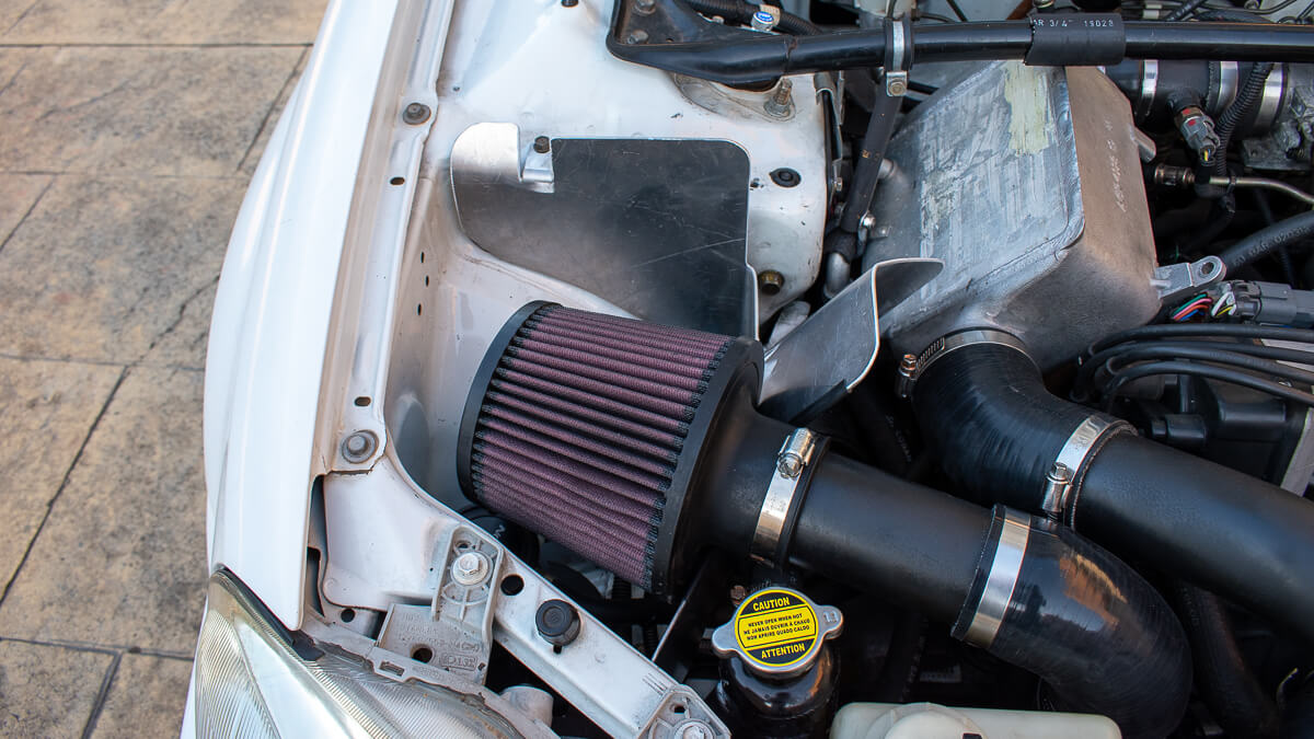
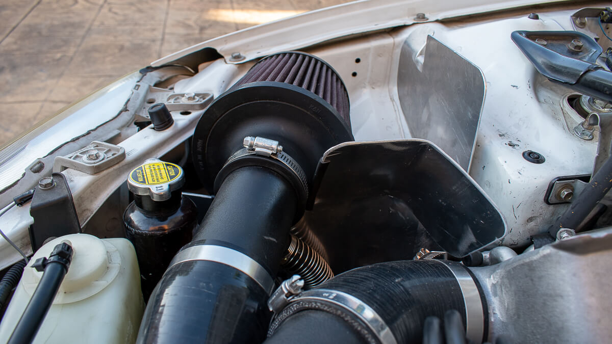
This complicated looking piece of aluminium in the engine bay is new. It’s purpose is to shield the air filter and approximate an air box.
The corner is folded out like that because we felt it could be beneficial for the W2A intercooler to get some cool air flowing over it.
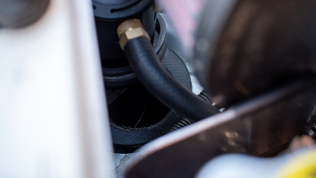
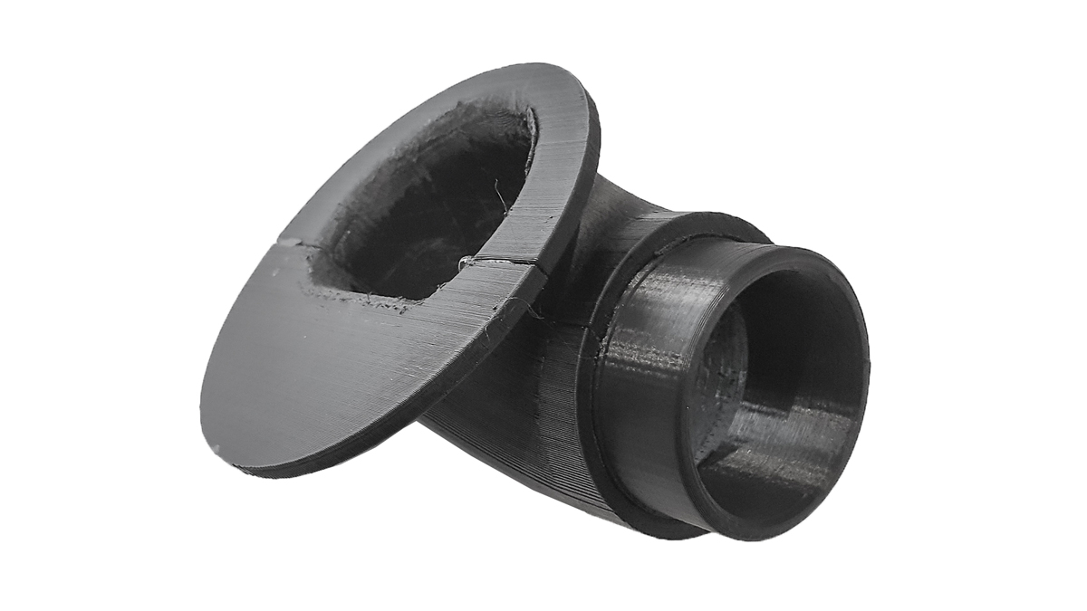
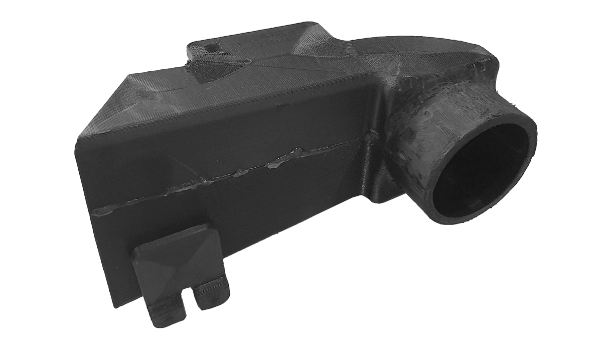
This is the engine bay outlet of a new cold air duct. This duct draws air from the front bumper to the underside of the air filter.
The duct was designed on CAD and then 3D printed from PLA with a 4.5mm wall and 50% fill density.
The Id is just over 50mm (2″).
This is what the engine bay side outlet looks like
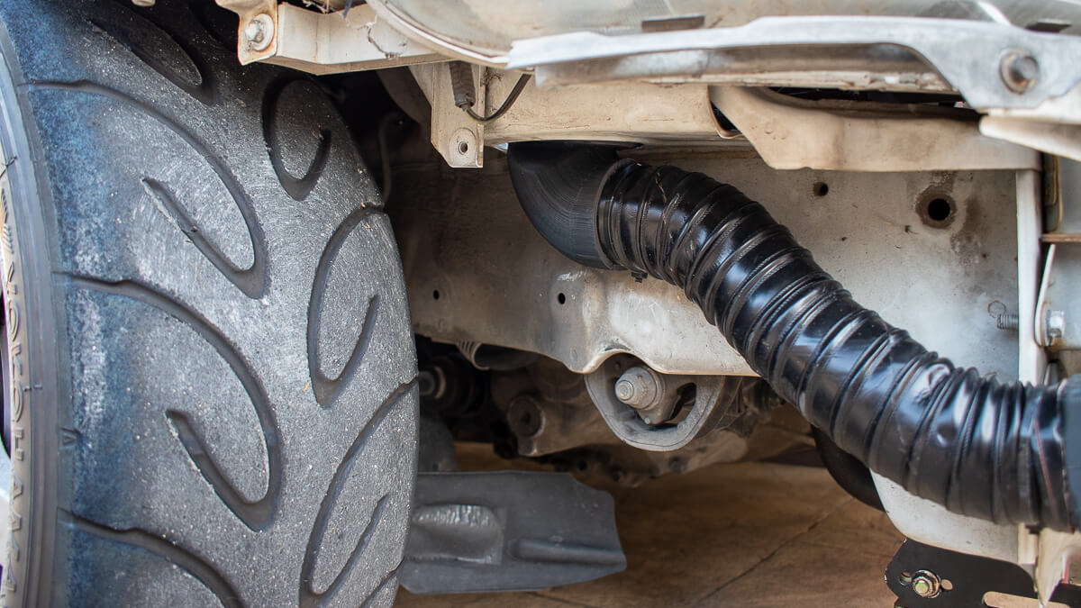
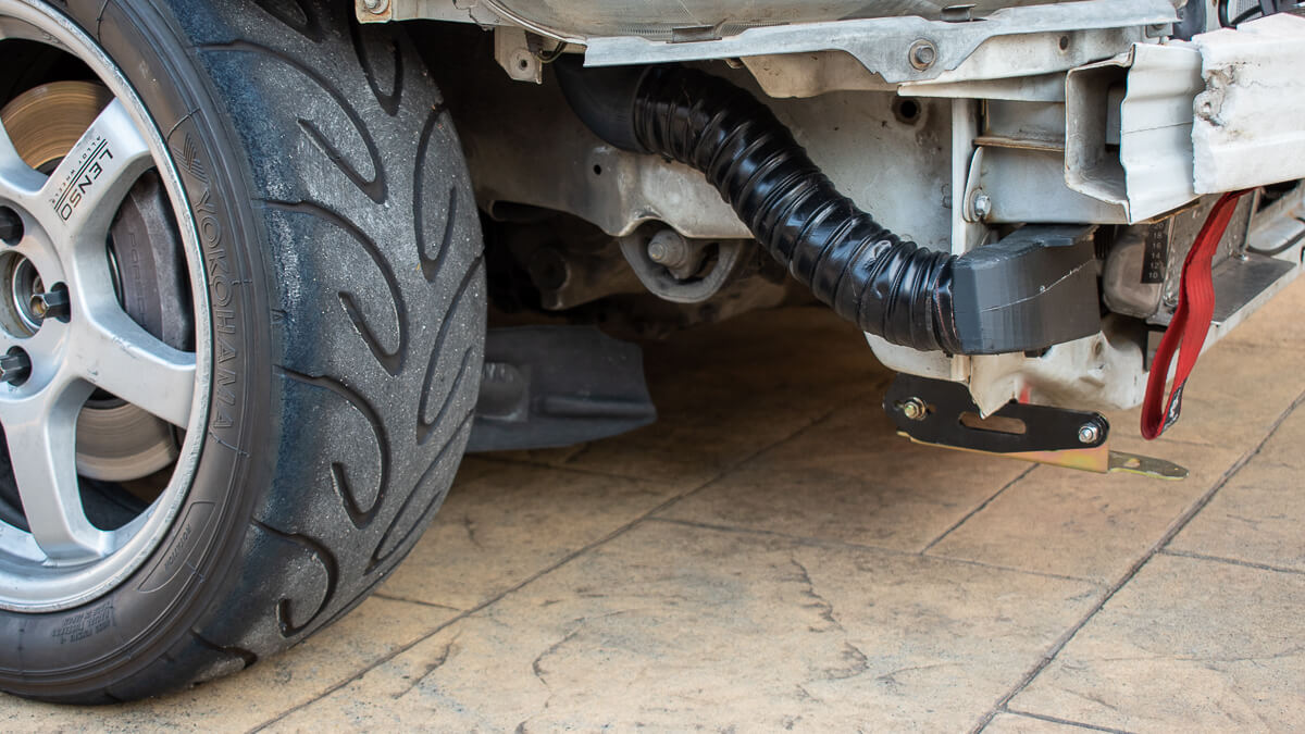
Leading into this outlet is a piece of 2″ black flexible hose. Similar deal with the inlet duct, the shape is driven from the limited space behind the bumper and needed to adapt from a rectangular inlet shape to then accept the 2″ flexible hose.
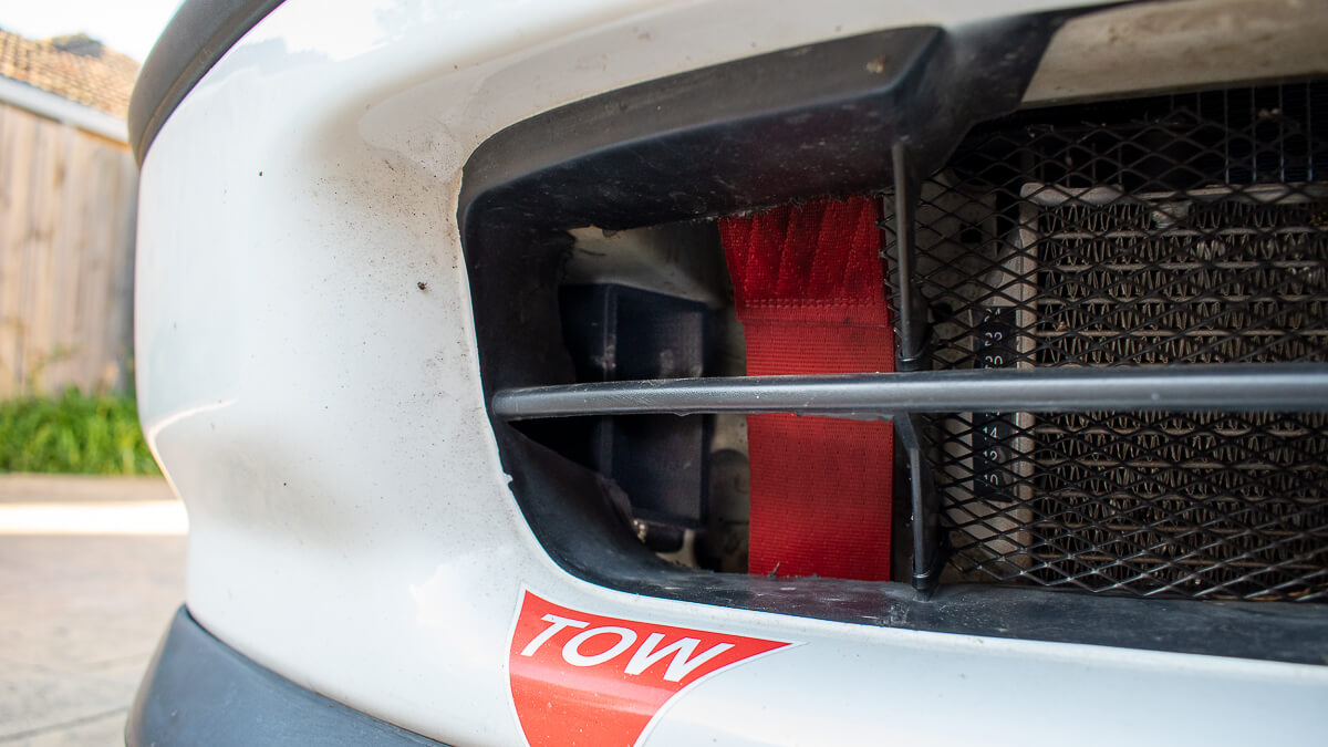
You can see the opening of the duct through the front bumper here. You might be wondering why the opening is not pointed directly forward into the oncoming air, this is not super necessary as the region in front of the radiator is a region of high pressure and air will flow from here into the engine bay just fine.
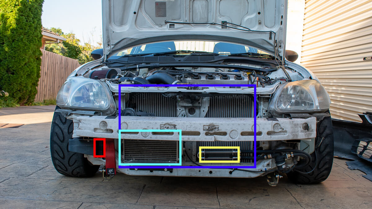
The front of the car is now packed, we have:
- Dark blue – full width, 50mm deep aluminium radiator
- Light blue – radiator for the water to air intercooler
- Yellow – radiator for the oil cooler (water to oil :))
- Red – inlet for the cold air duct
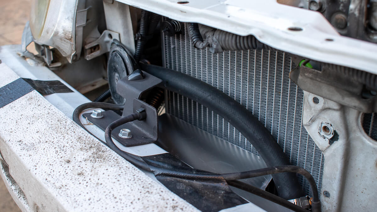
On this car we also have the ability to squirt water mist from the windscreen washer bottle on the radiator and intercooler radiator.
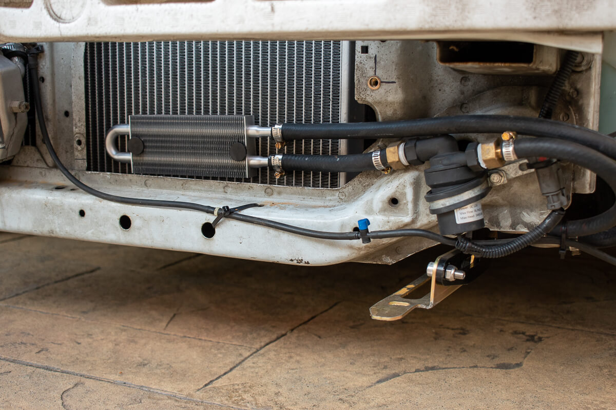
As a budget way to achieve some form of oil cooling we have fitted a b-series water to oil heat exchanger to the block (the one that goes between the oil filter and the block) and instead of routing water from the engine’s cooling system we have a stand alone water circuit with a 12v water pump to circulate the water. The effectiveness of this is not known but it was an interesting idea.
What’s next for this car?
We have a camshaft sitting on the shelf and it sure would be fun to get that installed and the car re-tuned, we now have sufficient cooling and air management to support a lot more power!