**This post has been transferred from my long running build thread on Honda-Tech.**
I’m going to re-post the thread on this site for the benefit of the people that are not active in the forums but will still appreciate the content.
The photos might not be as good as the more recent posts but there’s still some great content
If you’re interested in the Sedan build you’ll want to read up on the DC2 as well!
A lot of the customs parts such as the tie rod ends, brake booster delete and rear trailing arm modifications were developed on this DC2 Chassis
Enjoy the read
Cheers Grant
Ok, this is mostly a follow up to my previous post on bump steer but also may be of interest to those who were posting in Bazda’s thread about bumpsteer.
The first you need to understand what we are trying to achieve. Our Honda’s have a double wishbone front suspension and rack and pinion steering.
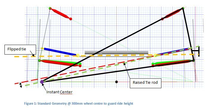
If you look at the image below, i have pulled a screen shot from Susprog 3d and overlayed some lines and annotations.
The way I visualize what is going on is to imagine that for this instance in time the thick black lines form a rigid member and the wheel pivots about the purple dot.
The purple dot indicates the instant centre, for every position of the wheel through its travel, this point is in a slightly different place
In theory, if the tie rod pointed at the instant centre, for all instant centre positions we would have no bumpsteer.
In the real world, the inner tie rod pivot is fixed relative to the chassis and the outer tie rod end point is fixed relative to the upright.
I’m not going to get into toe in vs toe out, slip angle etc in this post, rather just present the geometric implications of tie rod height on the upright.
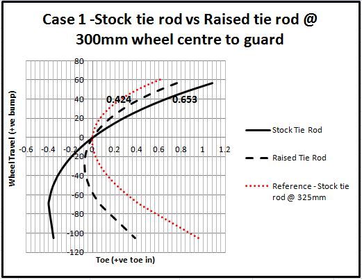
In the figure below I have plotted two toe curves for a Dc2 with a ride height equivalent of a car with 300mm distance from the centre of the wheel to the guard (CW2G).
The red dotted line is the toe curve with a ride height 325mm (WC2G) and is intended to show what a stock (slightly lowered) toe curve would look like.
The black dotted line is the toe curve for a tie rod end higher than stock and you can see raising the tie rod end has reduced the toe in with bump.
In these plots 0.2 deg roughly translates to 1mm of toe measured at the edge of the tyre for a 15″ wheel.
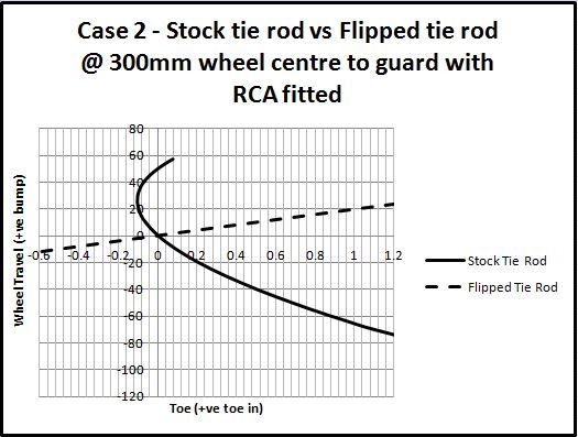
Case 2 is a dc2 with front roll centre adjusters fitted and with a ride height of 300mm (WC2G)
What is interesting in this case is that the wheel is toeing OUT with bump but the magnitude of toe change is rather small. This is why I suggest guys running RCA and stock tie rods arn’t having any issues with bumpsteer.
The dotted line on this plot is the result of fitting a flipped tie rod (one that mounts underneath the steer arm). Oh dear, significant toe change with wheel position. This seems really extreme to me and I suspected something was wrong with the
model. I went over it a few times and always got a similar result. I’d be interested to see the results of someone running this set up measuring their bumpsteer with DTIs.
So if a car is running an RCA is their any benefit to modifying the tie rod height? I believe so.
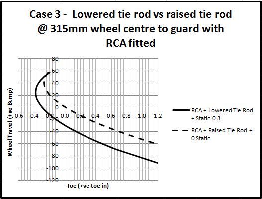
Case 3 shows the two scenarios that I intend to test on track.
The sold line shows the toe curve that i believe is going to net the best laptimes, a lowered tie rod with static toe out.
The dotted line is an alternate set up where you run 0 toe out but raise the height of the tie rod.
Just to ground this discussion in the real world here is a picture of a height adjustable tie rod set up as used by the Real Time Racing Dc2
this car…
RTR images do not belong to me. Sourced from descartesfool on Honda-tech
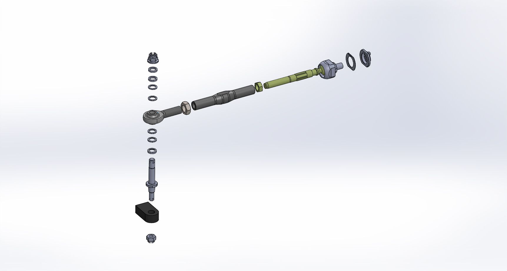
Having worked out what I needed I did a bit of research and found no one makes such a thing.
I discussed the Tie Rod idea with another Honda owning engineer (ChargeR) at the Winton track day and he mentioned he had been planning to make something up himself so we decided to develop the tie rod kit together.
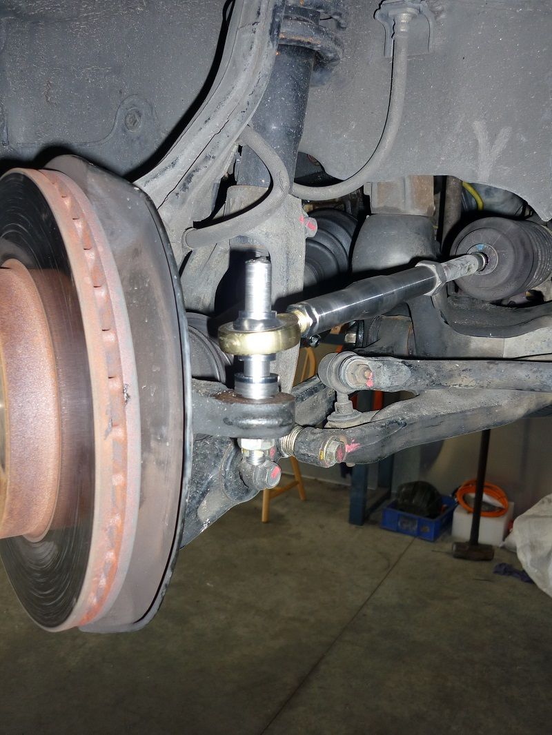
Those of you familiar with the stock tie rod will know it is curved to miss the back side of the wheel.
We didn’t want to make our link curved but also wanted to prevent the possibility of the wheel rubbing on the tie rod.
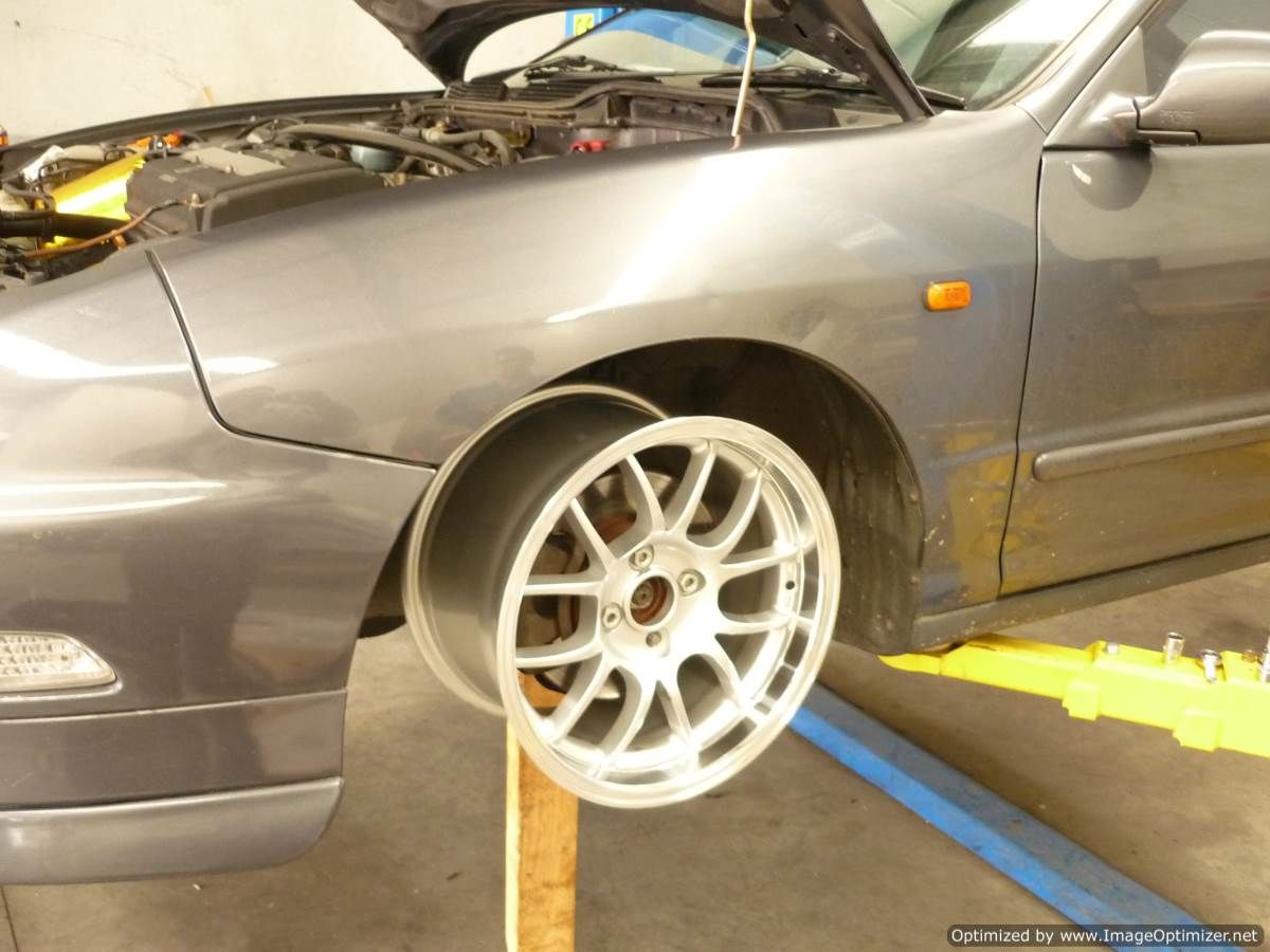
We test fit a 15 x 9 +36 and took measurements to work out what kind of spacer would be required to reduce the rack travel and prevent wheel on tie rod contact.
We came up with a design for the spacer and organised to get the tie rod kit components produced.
The last of the components are due back from heat treat this week and I plan to get my set of tie rods installed at the same time I install the powdercoated uprights.

